|
The 3D CAD Assembly Defined |
|
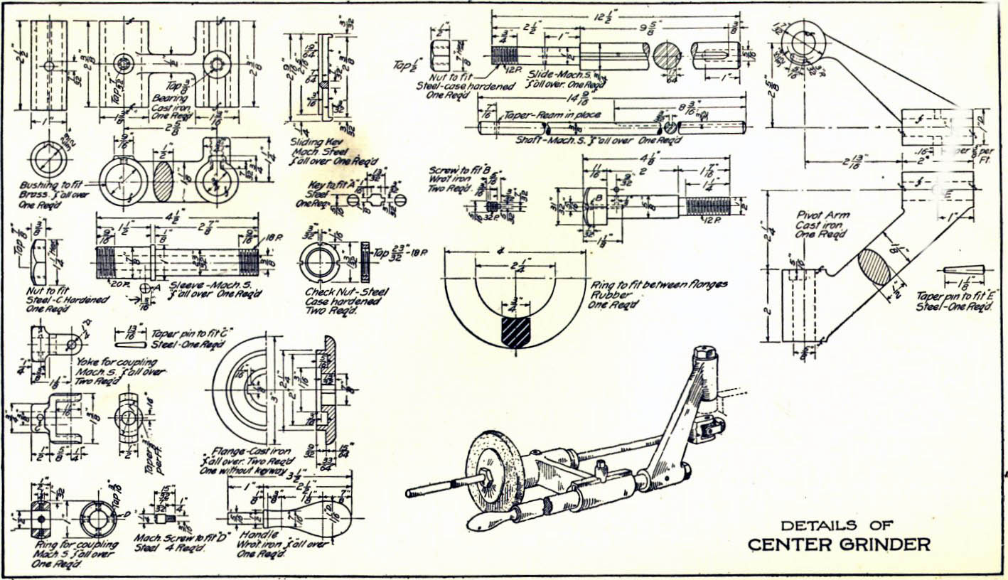
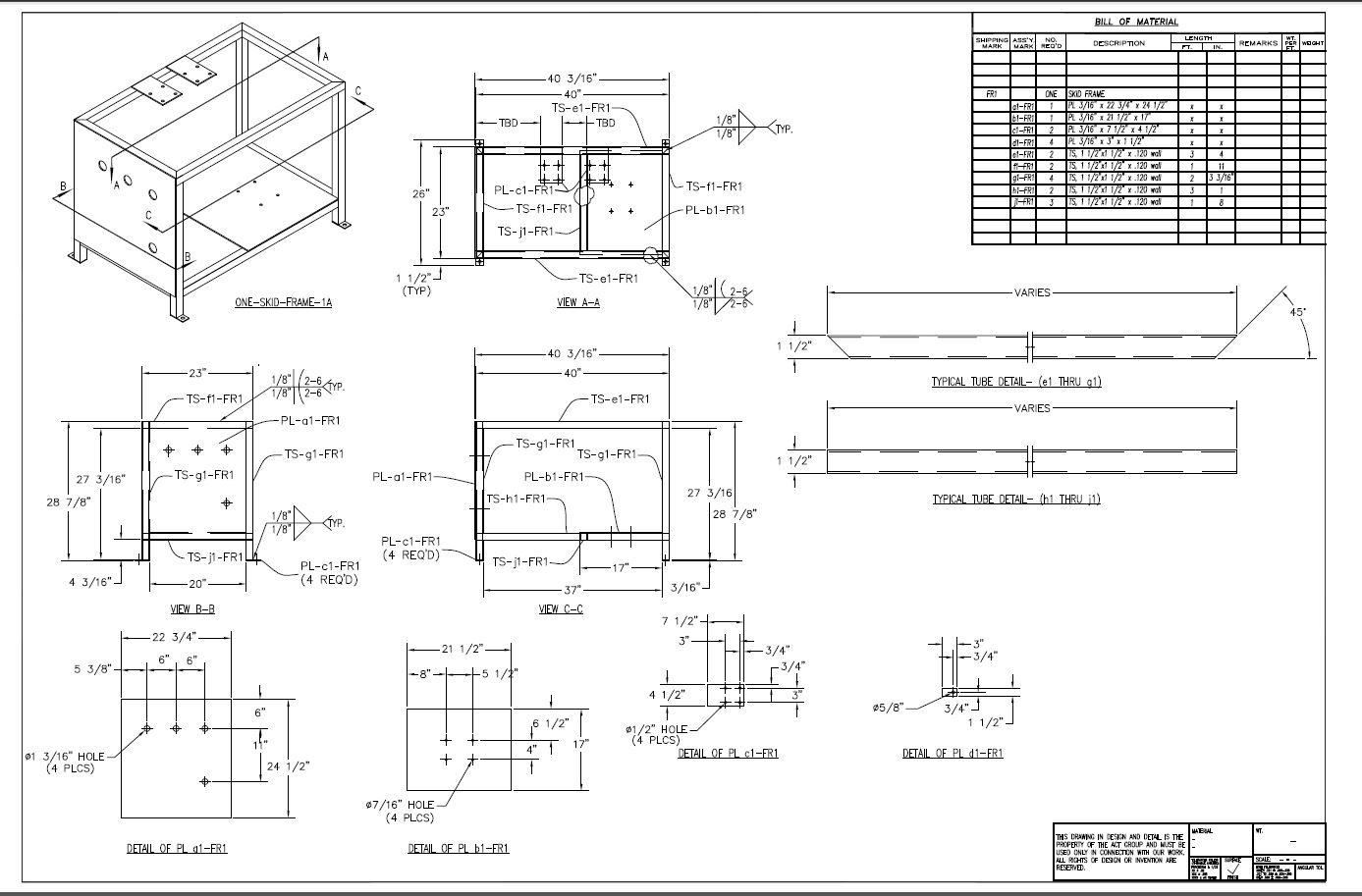
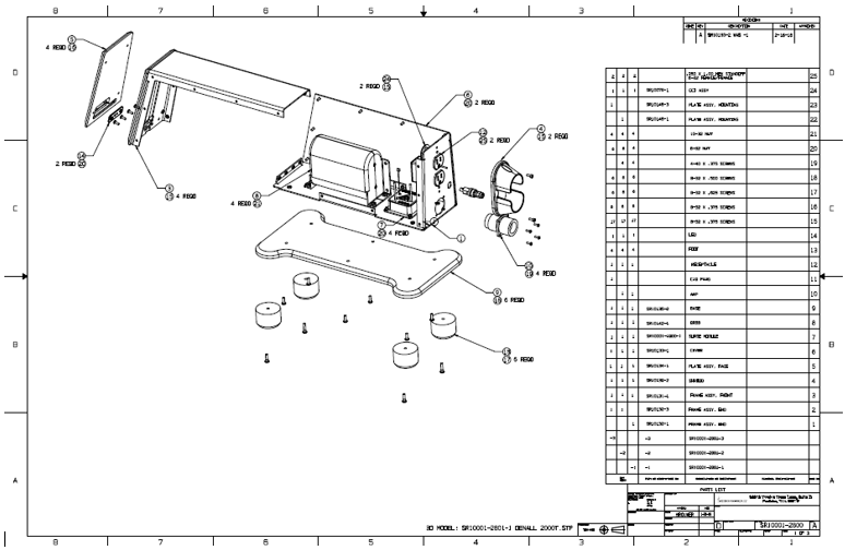
An assembly pre-3D CAD was just a drawing represented as a schematic of the parts assembled with a variety of standard, auxiliary and section views, somewhat of an illustrated parts list. It would come in a variety of forms, mostly orthographic views, but there were a few that would do isometric illustrations. The drawing was used by planning to develop assembly procedures. A good portion of the time they had the parts available. The ancient drawing below is called a detailed assembly with an isometric view showing how the parts were assembled.
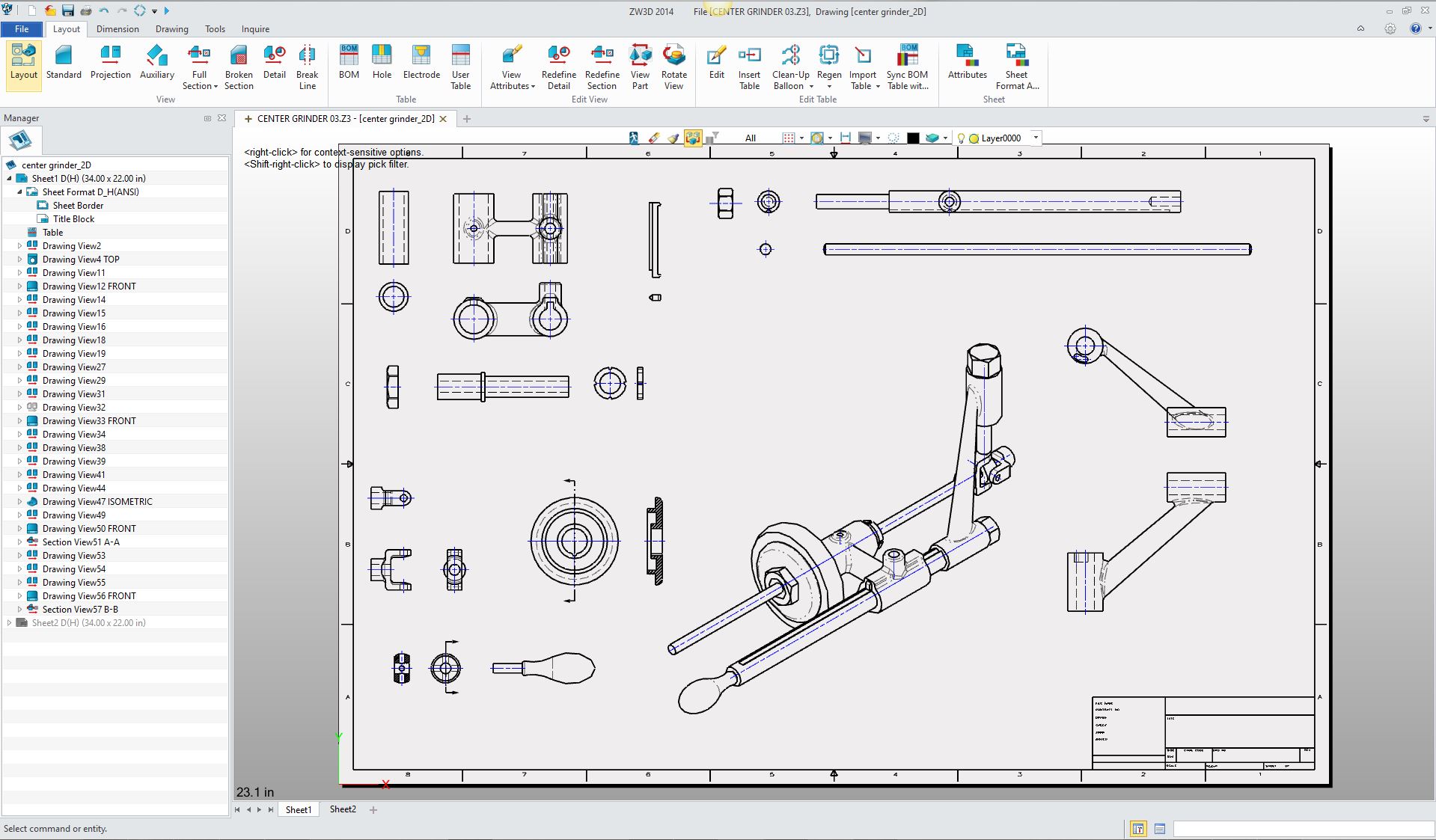
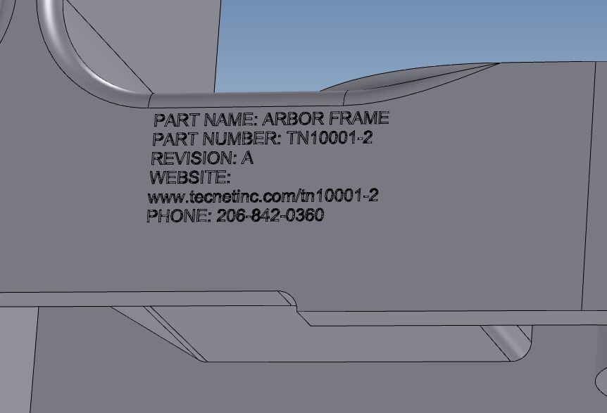
Here is an AID (Associated Information Document) of the above drawing sans dimensions and annotation recreated in ZW3D done in a single file.
But the manual isometric view was far too time consuming
and we depended on the the engineering professional having the ability to "read" a drawing: The ability to see the
part in 3D from the orthographic views. But you can see this
concept continued into the CAD world with Autocad, which of course was
nothing more than an electronic drafting package. Incorrectly call the “2D
Drawing”, this misnomer is still hampering our industry.
This is an Autocad drawing with a 2D created isometric illustration. Yes, a bit easier than on the board but still very time consuming. Realize this is an inseparable welded assembly.
But remember assembly drawings were mostly used
in-house or shared with closely monitored suppliers due to proprietary
reasons. The parts were denoted
by the part numbers or item bubbles. Item bubbles allowed much easier part
number changes. The part list was usually on the first drawing sheet but
could expand to other sheets as necessary. It was delivered as a blue print.
As computers showed up the the part list was also provided in the form of
computer printouts showing the assemblies, sub-assemblies and used on
assemblies that were available for a
variety of purposes in the company.
Today we have the 3D assembly which is nothing but an
associated part accumulator in the Solidworks clones. There are a few 3D CAD
systems that have a single model environment and have the complete assembly
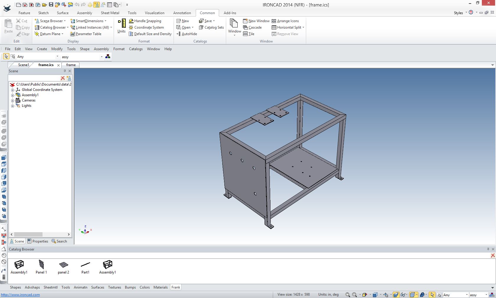
in one work space, such as IronCAD and ZW3D. The single model environment is much, much more productive when
working with assemblies. Both of these packages come with the option of having
external associated parts.
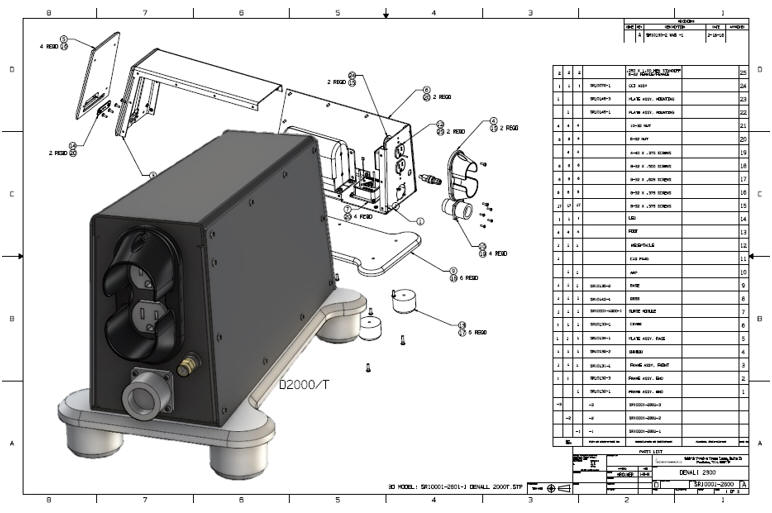
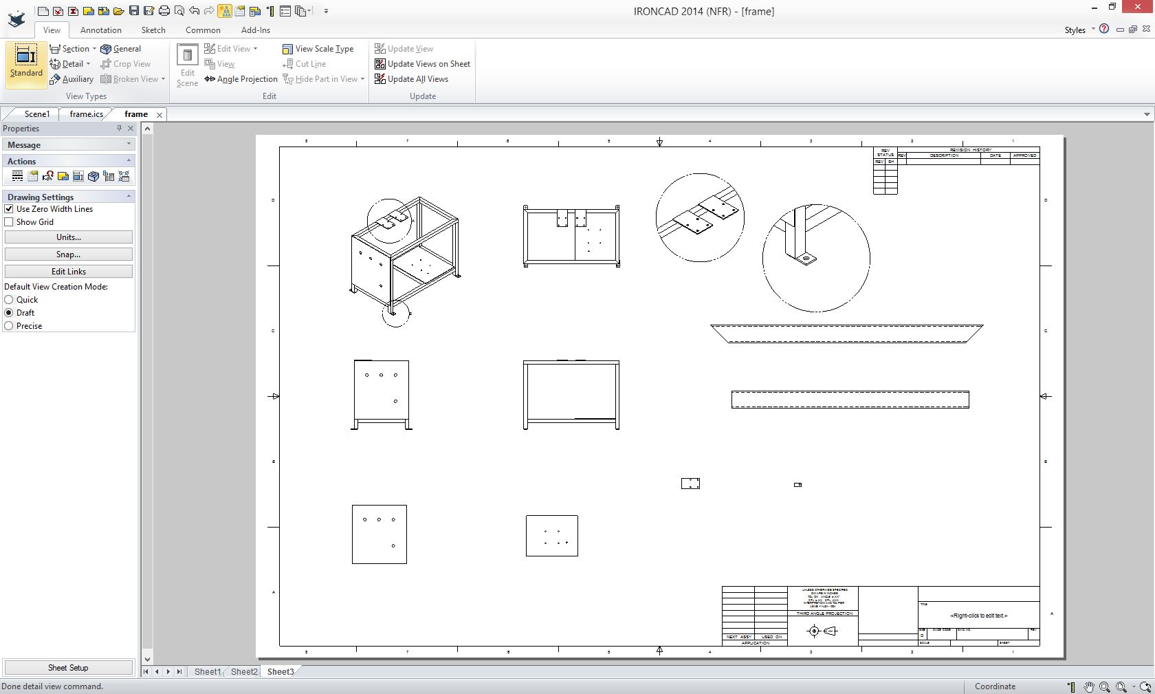
It is quite shocking to me to see the industry have such a problem with engineering documentation since it is so incredibly simple to create any level of documentation in the documentation modules. Engineering Documentation Today! The resulting AID sans dimensions and annotation, created in minutes. Yes they bought IronCAD. Many fabrications do not require CNC so the 3D model are not required. This throws quite a wrench in today's MBE (Model Based Enterprise)
Associated Assemblies in the
Solidworks Clones are problematic. You have to have all the referenced parts available. So
it is very important to plan the assembly. If there are standard or common parts
used where the link could be lost if the assembly file itself is sent out. Onshape only imports Solidworks in the Pack and Go .zip files. My favorite
import from Solidworks is exported as a Parasolid. I am not sure what format Catia,
Creo and Inventor export their assemblies, more than likely STEP. I have
read the native assembly files of those products without a problem. But all
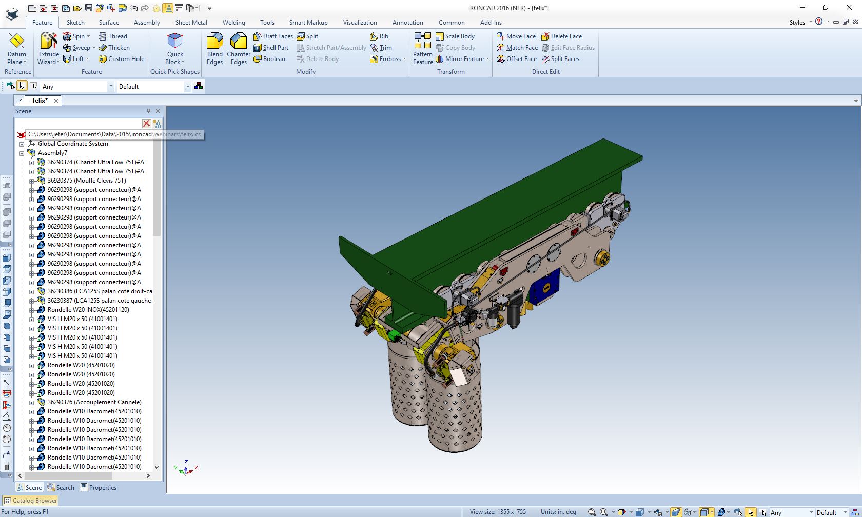
of the associated parts were all in the same folder. Here is a very large assembly imported into both ZW3D
and IronCAD.
So, what "HAS" gone wrong with Engineering? Part III
IronCAD
ZW3D ZW3D also imports the part and sub-assembly names 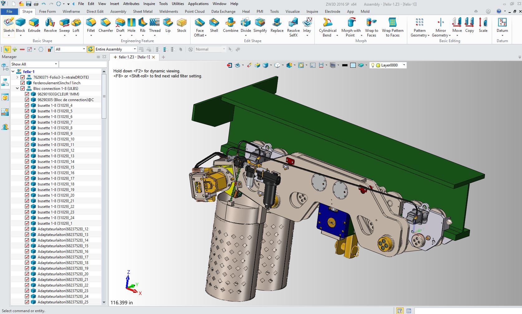 Handling Assembly Files Now we really should not be
passing assemblies back and forth. I believe they should never leave the
native system due to the engineering proprietary information.
PDM is a bit of a tough process and can be problematic.
I rarely comment on PDM since it is used only by those trained in the CAD
system whether integrated or a 3rd party outside system and in my opinion
should be treated like the drawing vault was in the past. We have the part file and the
associated assembly file in all Solidworks Clones. The parts always have to be accessible.
The major problem with engineering is the myriad of CAD systems we use. This locks many companies into non-productive history only based CAD systems. It may have been state of the art in 1988, but as we know many technologies advance with new 3D CAD products. Productive increases with the single model environment cannot be denied. Maybe their here now.
We can easily archive our assemblies in a non-native
neutral format and still keep the current information at the time of release
available. I
have defined this in this article. We just add what I call the embedded
title block.
Many of those that have very little applicable
knowledge think that the model is sacrosanct. It is hardly so. When you send a
part to CNC they may hide or remove many features. Most have very robust direct
editing 3D CAD software that allows this.
Once a standard is set up
then you can use any system to modify any of these parts in the
future. The future CAD system will produce basically dumb models that will
be modified with smart robust direct edit/hybrid modeling systems. They will not be limited
by the complex history only Pro/e paradigm. Just think of the cost savings. A common standard file
format that can be accessed by any system.
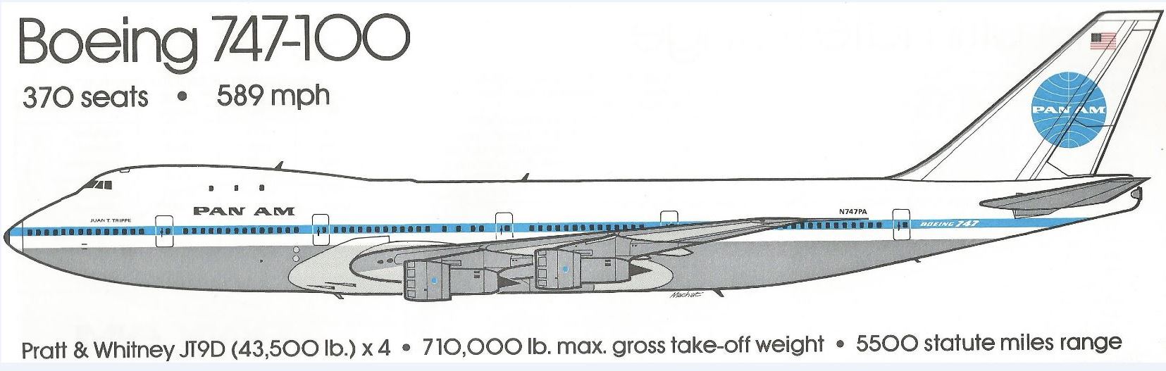
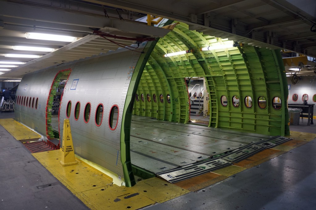
The Very Large Assembly What about very large assemblies? We never work on very large assemblies. If they even exist they are under the control of what you would call a configuration control group. Let’s take a Boeing airplane. Airplanes are built in sections each being a separate assembly. Each is assembled in a separate process. Do we need the complete assembled Airplane? Of course, not. But we could if we were willing to waste a lot of time and resources. "Airplanes are thousands of parts flying in close proximity!"
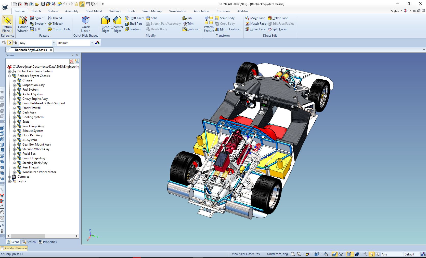
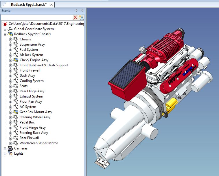
An airplane, an automobile or any large assembly is broken down to specific groups. In an airplane it is primary and secondary structures, controls, landing gear, wings, payloads, avionics etc. Automotive: brakes, power train (engine, transmission and other components), body, glass, electronics, interior, etc. Each group has their documentation coordinated with the different relative groups, making assembly much easier. Actually it is a somewhat simple process with a bit of documentation logistics in design with virtual parts and assemblies available and in manufacturing with the actual parts in front of them. Manufacturing planning is much, much easier today with the availability of a virtual assembly. But they really need a much more flexible system than a Pro/e clone. This is the Redback Spyder
Here is the scene browser: Notice even in this smaller assembly the sub-assemblies are separated. Shown here is the power train. Now these assemblies can be reference if we have different design groups making the assembly nothing but an accumulator for a configuration group that can control the overall project.
What do we "really" need? I feel it is time for the
industry to really step outside the box and evaluate how the CAD systems are
being using. The major CAD companies just have too much influence over
engineering and deliverable to manufacturing.
The Space Between Engineering and Manufacturing The CAD systems can be easily standardized. We have to
expand the capabilities of the system to a highly productive hybrid
modeling. Sadly, the current popular CAD systems are based on the dated
Pro/e paradigm that “CANNOT” incorporate this hybrid functionality locking
companies into a limited complex history only based system. Once we base our engineering on such a flexible
standard the possibilities are endless. This is how I have been designing for two decades. The Worst to Best 3D CAD System and Why 3D Modeling Techniques Defined The Future of Document Control
I had a comment on Linkedin
on my Onshape Posted Article.
Onshape! A View from the Clouds “These types of cloud based tools require your
information to be stored on line. what prevents the people/company from
accessing that information? I see a lot of stolen info.” My answer “Having the parts available on line would be just like
the blue print. The AID (Associated Information Document) as a PDF with the
3D model as a pattern. Assemblies would
not include the models since it is basically an illustrated parts list. So it would
be a chore to get all of the components for any assembly, mostly with
arbitrary documentation numbers. Remember, all
engineering is done in the native local CAD system. Now I agree doing your complete engineering on line would a too risky.” That comment made I start thinking about assemblies and what form they
are delivered.
OnShape type cloud system is a
basically a bucket where any type of information can be uploaded and stored.
This is the perfect Document Control system. You can upload the part in a
native format if it can be imported by Onshape and/or a neutral format with an
AID as a PDF. An interesting aside on this would be the But when we go to the Assembly we do not want to upload
the complete assembly. Only the documentation. This is usually a schematic
showing all the arrangement of the parts and a parts list. A few assembly
requirements like bonding, torqueing and other rigging instructions. But it
will be taken by planning and they will create planning orders. We see this
in assembly line or a group of mechanics assembling sub-assemblies. Rarely
do the mechanics work from the original engineering documentation.
Now we don’t care how the assemblies are handled inside
the 3D CAD system. I am only interested in how we present the information to
manufacturing. The only viable way is by what I defined above.
"The total purpose of engineering is to make available concise, Does manufacturing need a 3D CAD assembly model? Manufacturing needs to have access to the assembly files. I was contacted by Boeing planning, they were pulling their hair out trying to use Catia 5 for their planning instructions and were looking for an workable solution. I showed them that IronCAD could have the complete assembly in one single file and easily create any documentation they needed. I never could get to the decision makers. No one is interested in evaluating the existing system. Boeing engineering and manufacturing is in a world of "Work Around". It used to be the "Gem" of standard engineering and manufacturing. Today, the PLM gurus, InfoTechs and Dassault are in charge and all standards have been thrown out.
Engineering Documentation - A Primer for the PLM Guru! Update 11-22-2018 I have an old friend and associate (draftsman) working at a large aerospace firm. He was explaining that he couldn't make a change requested by the lead engineer because it would violate the company standards! The answer by the engineer: "Standards are only used for guidelines" True story! My friend just sat there with a stunned look! It could be so much simpler. Checking, Design Review, Manufacturing and Data Extraction! Small Update: Onshape has changed its policies which makes this concept a bit more difficult and costly. But if we created a standard where Onshape could profit it could easily be done at a very reasonable cost. Especially for large companies like Boeing. A bit more about Cloud based document
control. With the assembly delivered only as a PDF document, anyone
one that hacks a cloud based Document Control system would have a hard time
finding all the parts. Not an easy task. OnShape, or something similar, is the future of Document Control and will soon
replace the convoluted PLM system. The Future of Document Control Now don’t get this confused with using cloud based CAD
for your design package. There are huge problems.
Update: Onshape, now does not offer the 10 free projects. All work is public. If you can allow that then the collaboration option is still viable. But I am sure a few professional seats would be well worth it for large companies with large projects. Or a small group of designers with the available budget. In a nut shell: Assemblies are relatively simple and just need to have concise, complete and unambiguous documentation defined in an easily accessible format. And remember when a project is done (if small enough) this needs to be archived in a single file if possible. Only to be pulled out for the basis of a new product or for a future investigation as in any legal situations.
TECH-NET Engineering Services!
If you are interested in adding professional hybrid modeling capabilities or looking for a new solution to increase your productivity, take some time to download a fully functional 30 day evaluation and play with these packages. Feel free to give me a call if you have any questions or would like an on-line presentation.
Joe Brouwer |
TECH-NET ASSOCIATES | RENDERING OF THE MONTH | CAD•CAM SERVICES
HARDWARE | TECH TIPS | EMPLOYMENT | CONTACT