|
Engineering Ignorance Defined II Top 5 Reasons to Use MBD! DEBUNKED!  | |
 Engineering Ignorance Defined CONFUSED? MBE - Model Based Enterprise MBD - Model Based Definition Engineering Ignorance Defined III How to Define a 3D PMI Assembly You have got to be Kidding
Engineering Ignorance Defined IV
Engineering Ignorance Defined V Please have a look at my first article. Engineering Ignorance Defined "Oboe Wu is a Solidworks MBD product manager with 20 years of experience in engineering and software. He is an advocate of model-based enterprise (MBE) and smart manufacturing" Now, I do not like criticizing anyone directly, but as the the manager of Solidworks efforts on MBE he is quite influential. Check out Oboe's profile on Linkedin. There is no experience on engineering documentation. He has never made a drawing, created a 3D model and generated an AID (Associated Information Document (drawing)) or a PMI in a production environment. Never reviewed, approved and released any engineering documentation to document control and to manufacturing. He has made some very incorrect comments on how 3D MCAD is being used. Sadly, there seems to be no one around him that really realize how Solidworks and the 3D MCAD system has been used for over 36 years. The Death of the Draftsman or “Where has all the talent gone?” Oboe has a MSME and an MBA. Obviously he is very bright, but he groomed himself for management not drafting or even design engineering. Who in the world would put him in charge of engineering documentation? So, who would you look to? A draftsman, of course! Drafting, not engineering, was in charge of engineering documentation. Engineering documentation is in chaos. It is now being defined by those that have absolutely no applicable knowledge. Can Engineering Survive without the Drafting Group? I am available for consulting to help align the MBD and other documentation efforts of Solidworks or anyone else with today's engineering workaday world. Even though I an not a fan of Solidworks or any of the Pro/e (Creo) clones they can be used in a much simpler and more productive documentation standard. Any company could lead the way by establishing a new document controls system. There is huge profits by being the first to develop it. 3D Modeling Techniques Defined Standard Cloud Based Engineering Document Control Joe Brouwer 206-842-0360 Here is the original article Top 5 Reasons to Use MBD Here is the intro statement. "We are all very familiar with 2D drawings. They’ve been used for hundreds of years and they still work. Why should we bother with model-based definition (MBD)? What are the concrete benefits of MBD? Let’s have a look at the top five reasons to use MBD." First we have to define "2D Drawings". I really hate the term "2D Drawing". What other kind of drawings are there beside 2D. Drawing: A description of the part or assembly created by disassociated orthographically projected views. Below is an electronic "drawing" created in Autocad. Each of the entities is separately created, lines, arcs and splines. These Graphics come from "The Death of the Drawing" article. Calling Autocad, computer aided design is a bit of a misnomer since it was nothing but an "Electronic Drafting Package" (Computer Aided Drafting) as compared to the 3D CAD (Computer Aided "Design") packages most use today. With 3D CAD we have moved the documentation to the end to the process instead of being the process. 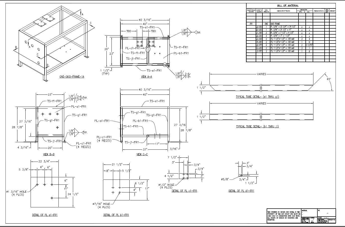 In 1982 I was introduced to Computervision CADDS ( Computervision Automated Design and Drafting System) 4 3D CAD system. The selling point of this system was we could modeling in 3D wireframe and then generate documents from the model. When we would change the model the document would change. Why do I call them documents? They were not drawings. We did not draw anything we modeled in 3D. I have coined these documents AIDs (Associated Information Documents). These are very easy to create and detail (add dimensions) and add required annotations, like notes and other information. Here is the 3D model of the above weldment done in an hour. 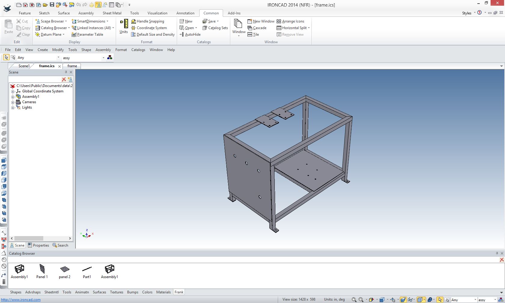 Now here is the AID generated from that model. I can easily put in the dimensions, notes and Part List (BOM). No more than an hour or two. 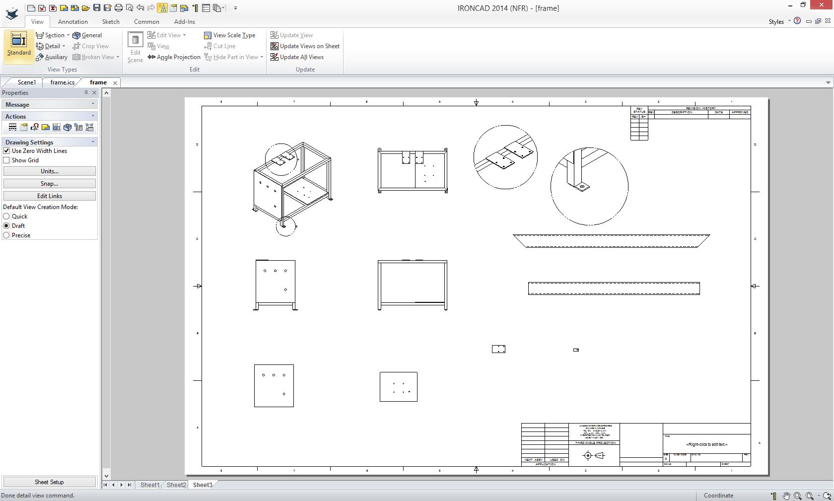 Oboe is working with Solidworks. Solidworks does not provide a standalone drafting (drawing) module. It provides a documentation module like I used above. This was IronCAD, but they both work identically. In fact Pro/e is also based on this documentation paradigm. To prove there are no drawing capabilities in Solidworks, Dassault has a Autocad clone called Draftsight for doing drawings. No not "2D drawings", just drawings. Okay, who is reading Oboe's article. Obviously not the experienced Solidworks designer that has created many AIDs. I see no comments about this in any of Oboe's articles where he has described the MBD process. We have been providing fully defined AIDs since the beginning of 3D CAD. The 1980's - 3D CAD - The Beginning For years the only product out of 3D CAD was the AID being delivered as a paper print. Autocad was creating drawings at the time and they looked just like the AID and, of course, were delivered as paper prints. Boeing called these the paper "Flat File" as compared to the 3D model that generated them. This is probably where the misnomer "2D Drawing" was created. In the late 1980's surfacing was introduce and the 3D model could now be used for a variety of purposes. It was being directly used by manufacturing to provide a pattern for the now widely introduced PC based CNC systems such as SmartCam, MasterCAM and SurfCam. But the completely defined AID or "Flat File" was delivered as a paper print along with the 3D model was the design authority. So when Oboe says we were using drawings only for our deliverable it is quite ignorant of what we were doing. 3D CAD has always delivered the AID. All 3D CAD systems provide a documentation module to provide the AID. Whew... sorry, but it takes a good knowledge of 3D CAD history to debunk such ignorance. Now, lets get started debunking the five points. 1. MBD further automates manufacturing with software-readable product and manufacturing information (PMI) I have a theory of why the PMI was created. It is by far the least thought through process in engineering. Remember Boeing was releasing the 3D model and the paper "Flat File" to their suppliers. How do I know this? I supplied every Boeing supplier in the Great Northwest at east one seat of PC based 3D CADKEY to be compatible with Catia 3 and 4. In the beginning they sent IGES for 3D wireframe and surfacing. Soon with the release of solid modeling the STEP. But they were still delivering the AID as a paper print or "flat file". The was the digital age and we were still delivering paper prints? With the release of Pro/e and history based modeling Boeing was having Pro/e envy. I was trying to get a couple seats of CADKEY into a new group at Boeing, around 1995, and the fellow asked "Is it history based?" I asked why would you want that? I have to tell you I was a bit naive about Pro/e after all no one was using it in the area. It was hugely expensive and ran on UNIX workstations. I thought, oh, oh... with the introduction of PC based Solidworks, history based modeling became the new "Buzz" word. Everyone one was talking about it. Boeing was using Boolean based Catia 4. This history was incredible you could just edit the dimensions. Sadly, it was more hype than performance. As we all know this paradigm is hugely complicate. There is only one constant in airplane design "change". But also there is a incredible turnover in engineering personnel. I assume even more with the elimination of the draftsman that were a very stable workforce. Their was virtually no management path for drafting and many retired out of specific groups. Where the engineer is always looking to move to management and other upward opportunities. Is 3D CAD Productivity an Oxymoron? Enter Catia 5 and PMI. Boeing probably confronted Dassault and said we have to have history based solid modeling. Dassault said we can create a Pro/e clone for you. They bought Solidworks and went to work. They came up with probably the worst airplane CAD software. The introduction of Catia 5 was a mess. There was virtually no plan. It was called Catia 5, yet was not compatible with Catia 4. They could not even import each others file. Catia 4.5 - The Catia incompatibility Solution Okay, okay back to PMI (Product Manufacturing Information) Boeing was delivering the AID as a paper print. They decided that they had to be totally digital and decided to get rid of the AID and the paper print. Now this was not a bad idea. But they were also battling document control. The model and the synchronized AID was causing a documentation management problem with the new Catia 5 PLM system. They wanted to only handle one file. They devised the PMI. Sadly, the PDF was right around the corner solving the complete digitalization of documentation problem. But the die was cast and we are still living with it. And Oboe has no idea how the PMI came to be. Solidworks introduced it just a couple of years ago. I have no idea why the "P" out of the InfoTechs always means product when it was obviously a part they were referencing. Do they have assembly PMI? This is a worse joke than the part PMI. The PMI was first released with all of the dimensions. Too cluttered. Then moved to basic dimensions and GD&T. I really don't know how GD&T got such a foot hold in the industry, it is overkill for most of the simple parts. But you never seen a complex PMI. Even that was too complicated and they moved to a minimized bastardization of GD&T. A bit of true position with massive amount of profile frames. Quite a huge humorous mess. I wills show you an actual working PMI from a large airplane manufacturing firm and an AID generated from the model. This was done in ZW3D that can read PMI files from most of the popular packages. You can see the complete article here. PMI vs AID Here is the PMI of and incredibly simple part, now made complex. 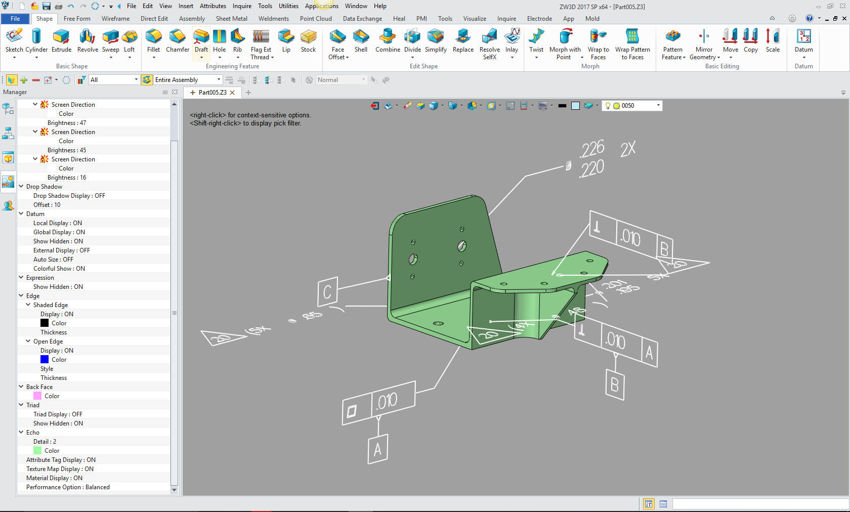 Here is the PMI documentation in the 3D Space. Please don't think how you access this information. There are 3D party software packages that turn these into AIDs. In fact here is a 3rd party quoting package with dimensioning capabilities to allow the suppler to get over all sizes. There are very few CAD systems that can import the PMI. Quoting Tools: CAD Dimensioning Another Band-Aid for MBE! 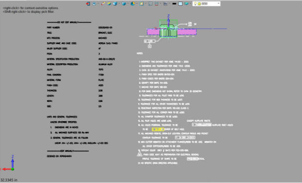 Here is the AID I created as a PDF. This only took 30 minutes. To complete it it would just take a couple of hours. But what Oboe seems to be ignorant of, is that Solidworks users and all other 3D CAD users have been delivering the AID and model to the suppliers for 28 years. Many suppliers will not accept the work without a 3D model and a fully defined AID.  Take a look at this chart. A "D" size drawing took around 24 hours on the board. An AID would take about 3 hours. A PMI? From the look at the example up above they may be right. 18 hours not counting the design time. Then add the limited accessibility as compared to the AID delivered as a PDF and the model delivered as the native or neutral format. 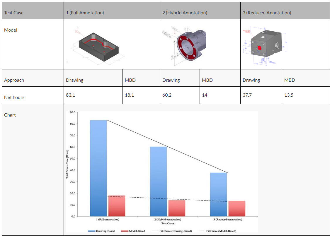 Even when they are only doing minimized GD&T the PMI would take 13 hours. The AID would take a little bit over an hour. I think these folks are comparing manual drawings. A Solidworks user doesn't even have drawing capabilities. Are they assuming engineers are designing with Autocad and not working in 3D? These are Solidworks employees and they seem to not know how their users are using the software. Take a look at this article: The Death of the Drawing 2. MBD increases technical communication efficiencies Again lets take a look at the first statement. "We all live in a 3D world and 3D is intuitive to us. When it comes to technical communications, we have to project 3D objects down to a 2D plane to author a drawing. Then, to interpret it, somebody else has to mentally reconstruct this 2D abstraction up to 3D again. This is a detour and it becomes excessive when you consider that most designs are built as 3D CAD models anyway." "We have to Project 3D to a 2D plane" No, we generate an AID and detail it. I am not sure where Oboe came up with concept, I not project anything since the old CADKEY wireframe days, uh 1987! It is not in the CAD lexicon. There is no 2D in Solidworks except in sketching. "Then, to interpret it, somebody else has to mentally reconstruct this 2D abstraction up to 3D again." No, we have not done that for decades that is the whole point of 3D CAD. Every CAD system has a AID module. Oboe has said this before and obviously does not understand how the 3D CAD system works including Solidworks. Mentally? What does this even mean? Who in the industry does not know how to read a drawing? Good Gawd, even engineers see drawings in school. But you know who has never seen a drawing? Oboe Wu. He has a BSME and does not know that it is a requirement for mechanical engineers to be able to read a drawing. The Boeing 787 did not use AIDs, they have a convoluted PMI system that is costing them a fortune. Change is the only constant in aircraft design. When the released documentation includes the AID and 3D model, it offers a much better format for review, checking and revision history. It is a much more defined and more clear documentation. And it only requires a compatible CAD system and an Adobe Reader. Boeing has not been based on the drawing for at least 32 years. I was there in 1986 and was PC based 3D CADKEY to the 747 Flight group. I am not sure it they were using "drawings" they wouldn't be further ahead. I have yet to see a Change Notice in PMI? In an AID it is just like a drawing, You have the complete revision history clearly defined. 3. MBD improves product quality This is by far the most ignorant of statements. Every part designed at Boeing in CAD since 1990 has had a 3D model with the AID or "Flat File". So there would be more quality with the AID because it is completely defining the part. As I showed above the PMI requires a compatible 3D system to scrutinize the part for quoting. As I have shown above, there is even a 3rd party quoting program for the PMI. 4. MBD establishes manufacturing competitive advantages Many suppliers have moved to MBD because the customer demands it. What do they need to access the PMI. A native system or approved viewer. Catia charges for the viewer. Solidworks has a variety of options. I think they are free. Today there is no standard for PMI including the presentation. PMI is only viable for machined and sheet metal parts. You never see assemblies. Just simple inseparable assemblies are much better on an AID where the component can be easily identified. Here is the basis for may next "Engineering Ignorance Defined" article. Yes, another Oboe Wu article on assemblies. How to Present the MBD Data of a Gear Box Assembly Just look at what a bizarre solution this is it. Do we really want to send a full native assembly file to final assembly? Of course not, we want a well defined schematic defined as an AID. In the past, with drawings, we would have to make orthographic drawings. With section views. Isometric views were out of the question due to the time they took. Take a look at an AID exploded assembly. All 3D CAD programs offer a way to create exploded AIDs. From the looks of it it would take much less time than the PMI assembly represented in the above article. The AID is a much more user friendly format that requires nothing but an Adobe Reader and a printer. You just have to not know anything about the current tools and how to use them to write such an out of touch articles. 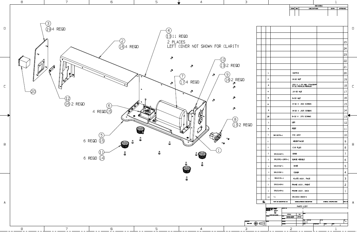 5. MBD unleashes the power of emerging technologies Take a look at the "Brilliant Factory". It is no different than before except we really didn't have manufacturing input after the released of the engineering. We had the draftsman, the lead engineer and draftsman, the checker, the stress engineer, the materials engineer and the manufacturing engineer. How many years of experience is there? This image is created by those that have no knowledge of the past engineering process. This is quite funny. I really do not know what he is talking about. He references 3D printing. Here is an article of a job I did in 1998, yes 20 years ago. We created 3D prints for urethane molds. Then revised the model for injection molding. THE PROTOTEK LINEFINDER You can see the two different configurations designed 10 year apart by utilizing the 3D model originally designed in IronCAD in 1998. So what is Oboe talking about. We have been doing this for almost 30 years, 23 years for Solidworks. Is there no one on the Solidworks staff any actual engineering experience or knowledge? Any look at Oboe's articles by an experience design engineer or draftsman would have seen the huge holes.  Conclusion It is shocking to someone that has worked in industrial/mechanical to see this lack of knowledge coming out of the most popular 3D CAD package on the market. I am sure that there are few of those that are using Solidworks that would not scratch their heads wondering what these folks are trying to say. But then Solidworks is not the only company, look at what comes out of PTC. It is like the live on Buzz Word never looking to see where they came from. PTC Creo Totally Misunderstands MBD And we don't want to miss more misinformation from Solidworks. Solidworks Totally Misunderstands MBD
|