I came across this promo in an email. As a 3D CAD/CAM dealer and enthusiast I am always interest in the latest information on all 3D CAD systems. I consider MBE (Model Based Enterprise) and MBD (Model Based Definition) a Band-Aid on a failed PLM system. You many not know what it is. MBE is a very expensive fraud basically played only on the very large companies. It is too expensive to be played on smaller companies. Most of us go happily on our way making AIDs (Associated Information Documents (drawings)) from our 3D models. Taking the model in native or neutral format along with the AID as a PDF and sending off to our suppliers. The article below shows why this incredibly convoluted system will fail. Why MBE/MBD/PMI Will FAIL Why MBE/MBD/PMI Will FAIL Part II But let's take a look at the above video. PTC seems to give the impression that you have the AID (Associated Information Document (drawing)) or the 3D model, not both. How many BUZZ words can they use in one video? But PTC is not the only CAD vendor that seems to misunderstand this concept. Watch as Dassault also gets it totally wrong. Solidworks: Totally Misunderstands MBE And you do not want miss this companion article. Solidworks: Engineering 4.0? The AID (Associated Information Document (drawing)) Note: I call them AIDS (Associated Information Documents) because we haven't drawn a drawing since we started using 3D CAD. The industry has been using this simple process since 1982 with the introduction of 3D CAD. This was the selling point of these early 3D CAD system, the AID or what the Boeing draftsman called the "flat file". Even PTC released Pro/e with this in mind. This single misnomer has cause an incredible amount of misunderstanding of the engineering process. The 1980's - 3D CAD - The Beginning In the video you first you see a couple of fellows rolling out a print, probably an AID (Associated Information Document (drawing)) generated directly from the Creo model as a PDF and printed. Now what is wrong with that picture? Nothing!! What is easier than reviewing a well defined AID (Associated Information Document (drawing)). No need to sit down at a computer with the native software. Actually, there is nothing more to say. The convenience of this format is just too obvious.
Enter MBE, MBE and the PMI (Product Manufacturing Information)
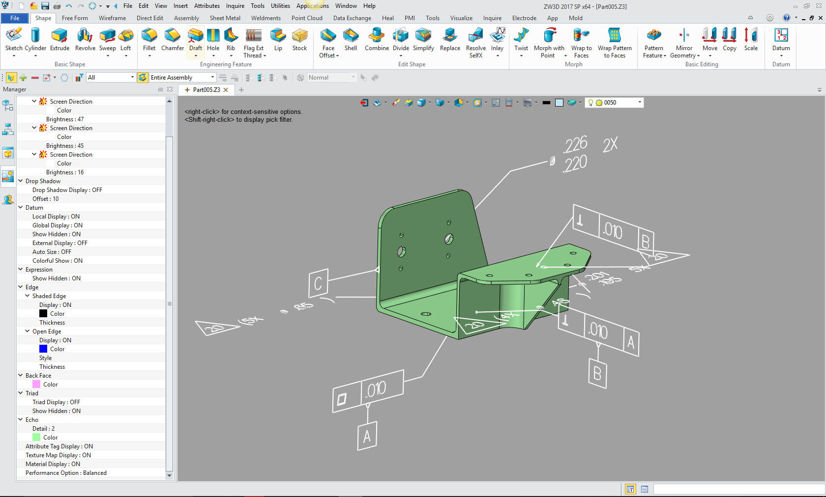
The PMI is truly the worst engineering deliverable ever devised. It was devised by people that have never done any design engineering or were responsible for releasing engineering documentation. They live in a world of abstracts not knowing what is important and what is not. Look at the PMI part. It only has GD&T (Geometric Dimensioning and Tolerancing). Not one reference to even the overall size of the part. You need a seat of the native software to really view the PMI. Now you have to sit at a computer or use a large presentation monitor. What?? What a fricking hassle. All that GD&T looks like gobbledygook. You can't even use it to quote parts. How do you train someone in GD&T, with this obscure application of this viable tolerancing system. To solve this problem one company came up with a 3rd party program work around. Quoting Tools: CAD Dimensioning Another Band-Aid for MBE! Sadly some of the millennial 3D CAD engineer can't even read an engineering drawing anyway, much less the minimized GD&T. This is one of the points to use MBD, because AIDs are too hard to read. Give me a break. Even a draftsman can read them! Update 10-2-17 This minimized GD&T does not lead to the understanding of tolerancing. When I was introduced to it in 1979 we already had a complete understanding of dimensioning and tolerancing. GD&T introduced feature control. It was a mixture of linear dimensionaing and GD&T. I am sure that many engineers today have never seen the original introduction of GD&T or even know what a a basic dimension is. All AIDs and Drawings are basically inspection documents. GD&T is not always required and many times not preferred. The only GD&T examples I have seen are single machined or sheet metal parts. I have not seen how they handle inseparable assemblies like weldments, riveted or bonded assemblies or sheet metal enclosures with fasteners, etc. Do they have the part list in the 3D space or do we now have to have a separate document? See the problems. It is like no one has any applicable engineering document control experience. Here is an obscure presentation of a PMI assembly. This shows a complete lack of knowledge of what the documentation is to present to manufacturing. How to Present the MBD Data of a Gear Box Assembly Suppliers? Oh, but wait! What if you are a supplier and don't have that software. Hmm Now we have a bit of a problem. There may be a viewer that can be purchased from the original CAD company at thou$and$. But the supplier has many customers. What if they are all using PMI? So maybe at an extra thousand bucks the supplier can buy a 3rd party translator that views the PMI from different systems. Now you have to have a maintenance on the translator. But wait, all of software packages have different versions released at different times. Could you ever get compatible with them all? Free PMI Importer? I sold a Boeing supplier a copy of CADKEY with a direct Catia 5 translator. They called me in a panic. "Joe, CADKEY will not read the Catia 5 file." They had a seat of Catia 5 (Boeing liked suppliers with Catia 5, but most suppliers didn't even use it) I said okay, load it into your Catia 5 and export it as a STEP file... Oops. Boeing failed to inform its suppliers they upgraded their Catia 5. 3D CAD and the 757 This is one of the main reasons why engineering documentation should not be in a proprietary native CAD format! It should be in a standard format that does not require any special software to view the PDF and use the 3D model. I just got offered a job to convert some Boeing drawings to 3D models. You just have to laugh. All the importance on the model being the authority and they give the supplier a drawing? The inmates are in charge of the asylum. All You Wanted to Know About Drawing to 3D Conversions But there is another problem. Many companies like Boeing demand that you use the native file (Secret: most suppliers don't). The Worst to Best 3D CAD System and Why Now, Boeing demands that all suppliers have a validation program. A program that compares the native 3D CAD file to the 3D CAD file that goes into the CNC. Apples to Apples? Of course!! Why?? Because Catia 5 delivers the more corrupt files than most 3D CAD systems. Compare and Validation Programs? Band-Aids for Self Inflicted Wounds! Corrupt 3D CAD Parts I will reiterate a few things here. Due to being based on the archaic PTC Pro/e paradigm of the separate part, assembly and AID (Associated Information Document (drawing)), the MBD and the PMI is a failed solution devised by the ignorant PLM folks to ease the data management problem by eliminating the separate AID (drawing) to maintain with the 3D model. All of engineering and manufacturing is suffering under this unnecessary complicated, convoluted, and costly chaotic mess! Engineering Documentation - A Primer for the PLM Guru! There are a few 3D CAD products on the market that have an integrated associated information document (drawing) included in the part or assembly. Think this through if you had a the associated information document (drawing) in the same file as the part do you think anyone would waste their time on MBE and PMI? Engineering Ignorance Defined Two Top 5 Reasons to Use MBD DEBUNKED! Minimizing the engineering documentation down to the tight tolerance dims and just putting profile GD&T frames all over do a disservice to the designer. Here is a comment from a BSME PE on this article when I posted to Linkedin. "The big problem is, any failure will be blamed on the responsible engineers and not an unworkable system. MBE is already being backstopped by drawings in many organizations that are forced to use MBE, but the drawings are frequently not in the release control process because they are not the "primary" data driving fabrication. A fine mess.." A completely detailed associated information document (drawing) provides a second check on the design for errors and maybe a better design. The PMI does not offer the necessary clarity for checking or reviewing the part.The ADCN (Advanced Drawing Change Notice) vs MBE In Conclusion: These decisions have been made by those outside of everyday engineering. The are made by MSMEs, PHDs and InfoTech gurus who sit in their ivory towers trying to short cut our precious engineering and are succeeding, costing the industry billions in wasted man hours and incorrect parts. Probably supported but the CPA bean counters. Sadly even companies the size of PTC that have been delivering 3D CAD for 30 years do not understand this concept and fall for the latest buzz words written by employees decades removed from the original purpose of the company. We need to put engineering back in charge of engineering! Okay, Okay, you think Joe is full of it and PMI is the way to go. Well PTC and the big boys are not the only ones that deliver PMI. ZW3D also creates PMI. But as you can see ZW3D also automatically presents the PMI information a conventional associated information document (drawing). One thing ZW3D does over Creo 4.0. It can import PMI data from, yes, Creo, NX, Catia and Solidworks. Sadly, they do not automatically convert imported PMI to the 2D sheet. It also has the AID (Associated Information Document (drawing)) integrated into the design file. Yes, you just click an icon and there you are editing the associated information document (drawing). You don't have to wonder if there is an associated information document (drawing) like you do with all the Pro/e clones. It is always there with the part or assembly. Imagine how much easier PDM and PLM would be?? All the pertinent information and more in an easy to read document. Engineering Ignorance Defined Two Top 5 Reasons to Use MBD DEBUNKED! Wait I am not done yet. ZW3D Lite basically matches Creo 4.0 in capability and priced at $2,000.00 with rental starting at 6 months $375.00 and 12 months $600.00. PTC is now subscription only, Price? $2,200.00 Plus year. Yes, it's time for you to take a serious look at what you are spending on your 3D CAD solution. PTC is betting you have more money than brains. ZW3D Pricing But wait, PTC is going to a subscription only! What are the ramifications to that?
But I have a much better solution for a standard engineering deliverable and document control that can save the industry millions if not billions in reduced software, personnel and management costs. The Fourth Engineering Deliverable The Future of Engineering Documentation The Ultimate Document Control System Standard Cloud Based Engineering Document Control
If you are in an engineering management or academic position and you would like to explore other related CAD subjects please feel free to peruse some of my other related articles. Viewpoints on the 3D CAD Industry Or give me a call
TECH-NET Engineering Services! If you are interested in adding professional hybrid modeling capabilities or looking for a new solution to increase your productivity, take some time to download a fully functional 30 day evaluation and play with these packages. Feel free to give me a call if you have any questions or would like an on-line presentation. |
TECH-NET ASSOCIATES | RENDERING OF THE MONTH | CAD•CAM SERVICES
HARDWARE | TECH TIPS | EMPLOYMENT | CONTACT