|
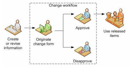
ADCN (Advanced Drawing Change Notice) |
|
I am a Boeing trained
draftsman. At Boeing we had the ADCN (Advanced Drawing Change
Notice) this was by far the most productive engineering change document ever
devised. When you are building airplanes, you are on a schedule
and must keep the assembly line moving. Due to the nature of the beast,
airplanes have different customers with different configurations. This
opens the door to mistakes. Any errors in design must be handled quickly and
efficiently. Boeing devised the ADCN to handle this problem.
Let’s look how an error is found.
The rejection tag is delivered to the responsible
engineering group, such as structures, flight deck, payloads, wing,
etc. In the past, it was given to a draftsman to research. They would come
up with a solution and prepare the documentation. THE ADCN The ADCN was the preferred document. It was done on
one or more “A” size, 8.5 x 11 vellum sheets. It would go through the
complete checking and sign off process. Then be released to document control
that would print it and attach it to the blue print or Microfiche of the
affected part or assembly. This was incredibly fast as compared to checking out
and revising the drawing. The changes were expedited out to the affected
parties in days. The supplier would receive the ADCN and attach it to the
print. They would instantly implement the change. When there were slow periods in the group they would
assign a new draftsman to incorporate the ADCNs. It was great experience.
This was called the DCN (Drawing Change Notice) and done on the original
drawing that would be checked out of the vault. This would create a new
revision letter. Now many times new design
requirements would demand the direct changes to the drawing. It was a bit of
a pain to do this because you would be responsible to incorporate the
outstanding ADCNs. It was very smooth operation. MBE (Model Base Enterprise) MBE came into being at Boeing
at the turn of the century with the introduction of Catia 5 PLM. This is where
the 3D model becomes the design authority.
We have been using the 3D model as a pattern since the
late 1980’s with the introduction of CNC. First, we supplied a 3D wireframe
for 2.5 axis milling, then 3 Axis with the introduction of surfacing and then,
of course, solid models. Using the solid model as the design authority has
huge problems. Imagine the above scenario
with the 3D model. The new 3D CAD engineer gets the rejection tag. Boeing
eliminated the drafting group years ago, allowing the draftsman to disappear
by attrition. You hand it to the least experienced engineer, since it
probably considered busy work. You do not get an engineering job at Boeing without a BSME!
Now, of course, since we have no drawings!!! WHAT? NO
DRAWINGS? Yes, Boeing moved to MBE which has eliminated the drawing even as a supporting document.
I am sure the PLM (Product
Lifecycle Management) folks quickly found that trying to keep track of two
synchronized files, the 3D model and drawing daunting. Actually these were
not drawings, they were AIDs (Associated Information Documents) based on the
3D Model. So, they decided to eliminate the AID all
together and replace it with what? Sadly, all PLM geniuses and Infotech
gurus think all CAD systems are the same and they must design a PLM system
around the CAD system. OMG, that is insanity!
The Solution? Let me introduce the PMI (Product Manufacturing Information). This has to be the biggest joke on engineering since, UH, I don’t think there has been a joke on engineering. Engineering documentation was in the hands of the draftsman. They have created, maintained and supported this ancient art since the very beginnings of the documentation of engineering. I am sure they never consulted Drafting, the only ones that truly understood this process when implementing MBE. If fact, they said: WOW! NO DRAWINGS = NO DRAFTSMEN!!
Boeing quickly
eliminated the Drafting and Document Control and
In this MBE world,
I have no idea in what form the liaison engineer gets the rejection tag to the responsible group. He can’t pull out a drawing
to review. Doe he have to have access to a seat of Catia 5 or Enovia? Hmmm,
I just don’t know. How does he communicate the error? Does he modify the parts directly? How does in mark up the changes with a PMI? I did ask a Boeing representative this question at a
seminar. He said “Yes that is a problem we have to work on”. Okay, the rejection tag is now delivered to the responsible group. Now the new 3D CAD engineer must research the problem. Hmmm, again no drawings. I suppose the engineer just brings up the native assemblies and works through all the 3D models and PMI's. Easy to view prints? Nope!! He has to view the native CAD file. Hmm How do you compare 3D models as PMIs? Time consuming beyond compare? The engineer finally comes up with a solution and
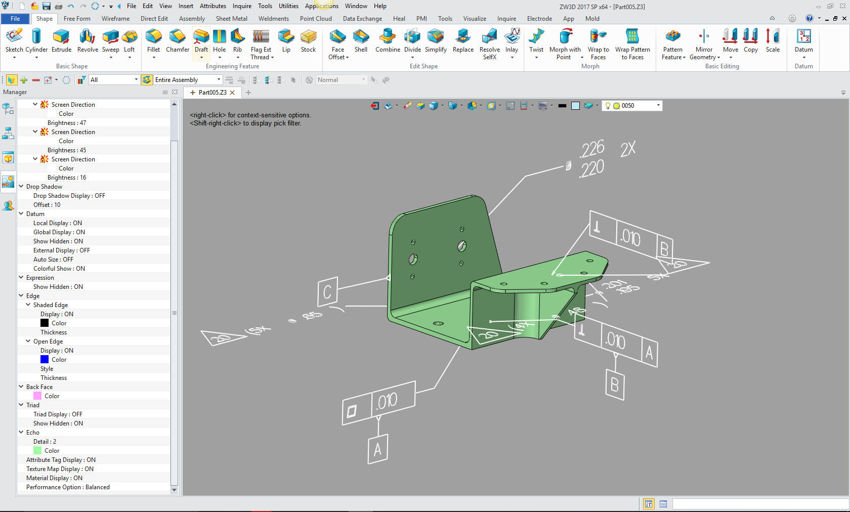
starts changing the 3D model. CHANGING THE 3D MODEL??
Here is an article that shows the heavy costs associated by depending on the CAD system to manage your engineering. The Worst to Best 3D CAD Systems Expanded! The engineer makes the
changes. Now, we hope there has not been some overlooked missed feature.
Hmm, do they have to do a comparison of the original and the new 3D model? How
do they document the changes? So instead of a fast ADCN, we now must directly change
the 3D model. There is no drawing to mark up. In the past, we could trust the
supplier to modify the drawing but the model is now sacrosanct? How
ridiculous is that? Oh, I forgot, the only way you could change the model is
with the native software. Oops!! Nobody thought this through? I have worked with many
Boeing suppliers that used IronCAD or ZW3D and would modify the 3D models for
CNC programming. Does Boeing know this?
Boeing now demands that the supplier runs the native Catia 5 file through a 3rd party validation program to assure that the 3D
model
is the same as it goes into the CNC program. This process creates an 8.5 x
11 report that has to be kept as a record. Funny, no Boeing audit has ever
been done. Yet, they demand that the supplier spend around $5,000.00 for the
privilege of creating parts for Boeing.
Now add the requirement to read the PMI?? PMI? how do
we read the PMI? A seat of Catia 5 with the same release as the PMI, Enovia,
Dassault’s expensive viewer, a third-party viewer, costly and you have to
keep up to date with the latest Catia version. What if you have different
customer using different software, like NX, Creo or Solidworks? We can only
hope that they all release their new versions at the same time. OMG! What am
I, some kind of comedian? More about the PMI The PMI is what these PLM geniuses and InfoTech gurus came up with to lessen the documentation data management problem. Have you seen these things? They have minimized the information to a point of silliness. Anyone that would consider the PMI and MBE as a serious engineering documentation solution: DOES NOT UNDERSTAND THE PURPOSE OF ENGINEERING DOCUMENTATION!
So, the idea of the PMI was that data management would
only have to maintain one document. WOW, JUST LIKE THE DRAWING!!
Oops… The PMI format is so obscure and inadequate that Boeing has 2 or more other documents that must travel with it. Sadly, these important other documents are referenced on the PMI, but usually not available to the outside supplier. PMI vs AID (Associated Engineering Document) From an almost instant
document, the ADCN, to a convoluted change that probably takes weeks, maybe
months. Then send it to the supplier that has to reprogram the 3D model. What
has Boeing saved?? The Future of MBE? The model based enterprise with crumble on itself as the 3D CAD systems disappear. Nothing last forever. There may be a much more productive system show up. Why in the world would we tie our engineering department to a CAD system. Don't ask the CAD vendor. They are not experts in how your company should be run! Their interests are in keeping you in the dark. Sadly, most CEO do not have the experience to challenge them. It all has to do with knowledgable questions. You cannot base your engineering deliverable Just think this through for once. The AID (drawing) or PMI is not for the engineer! It is for a multitude of other departments to use, such as manufacturing, purchasing, tech pubs, sales, marketing, product planning and yes engineering itself. Wait a minute, Joe, engineering has access to the original CAD files. Yes, but you want to access the "released" engineering documentation? It should be in a much easier accessible, usable and stable format. Hopefully a drawing and a model. We do not need access to the 3D assemblies. We just need a complete presentation how the parts go together. Any access to the native assembly should only be for change. Here is a comment from a MSME PE forced to used MBE: "The big problem is, any failure will be blamed on the responsible engineers and not an unworkable system. MBE is already being backstopped by drawings in many organizations that are forced to use MBE, but the drawings are frequently not in the release control process because they are not the "primary" data driving fabrication. A fine mess.." Could we implement something like the ADCN today? Of course, we could, we just use the 3D Model and
AID (drawing) as the
authority again. An AID (drawing) releases as a PDF and the 3D model are nothing more than an
inspection device.
As we try and short cut engineering we open the door to
Mr. Murphy to raise havoc. The AID (drawing), now nothing more than an associated information document generate from the 3D model, is very, very easy to create. But it offers much, much more than the 3D model.
So, there you go! I figure the large engineering companies will start
waking up and reevaluate this convoluted PLM/MBE system. I just hope all the old
draftsmen are not gone by that time.
Again, You cannot short cut engineering. That is the
problem with those that have not done any engineering and have not been
involved in the release of complete
engineering documentation. They do not know the ramifications. Bad parts!! I believe 3D CAD is less cost effective than using the drawings in the past using the PLM/MBE system. There has been too much dependence on the 3D model, which really is nothing more than a pattern, yes, yes, I know a very useful pattern. But engineering documentation is much more than some feature control frames in a 3D space. Boeing started out on the wrong 3D CAD foot in the late 1980's. Today, there is not enough applicable knowledge to pull them out of this huge costly hole they have dug with the help of Dassault's PLM and Boeing Computer Services. I have worked with Boeing and Catia for over 30 years. Dassault is responsible for keeping Boeing one of the most ignorant and isolated manufacturing companies. Their lack of interoperability is beyond belief. Again I will reference these two articles to prove my point! CADKEY or Catia? Boeing’s Billion-Dollar 3D CAD Mistake! The Worst to Best 3D CAD Systems Expanded!
TECH-NET Engineering Services! Why TECH-NET Sells IronCAD and ZW3D For more information or to download ZW3D or IronCAD
|
 On the Boeing assembly floor,
there are specialty engineers called liaison engineers. It is pronounced L”eye”ison in the aircraft industry (except maybe in France). They are called to a situation when
something cannot be installed. Now, it is not always a problem with the
engineering, it could be a problem with planning. The liaison engineers
purpose is to solve the problem temporarily by writing and drawing up a
rejection tag noting the change. This is part of the airplanes history.
Remember, we must assume the next plane may have the same problem. So the
faster we can get this change permanently implemented, the better.
On the Boeing assembly floor,
there are specialty engineers called liaison engineers. It is pronounced L”eye”ison in the aircraft industry (except maybe in France). They are called to a situation when
something cannot be installed. Now, it is not always a problem with the
engineering, it could be a problem with planning. The liaison engineers
purpose is to solve the problem temporarily by writing and drawing up a
rejection tag noting the change. This is part of the airplanes history.
Remember, we must assume the next plane may have the same problem. So the
faster we can get this change permanently implemented, the better.

TECH-NET ASSOCIATES | RENDERING OF THE MONTH | CAD•CAM SERVICES
HARDWARE | TECH TIPS | EMPLOYMENT | CONTACT